MECHANICAL ENGINEER
Desktop Lathe (MIT 2.72)
About the Project
This project was done as part of MIT's 2.72 Elements of Mechanical Design class. I was put in a team of 5 people and required to design and manufacture a desktop lathe capable of cutting aluminum with 50 micron repeatability.
My Role
I was the CAD and manufacturing guru of the team. This mean that I was primarily responsible for the design and manufacturing of the overall lathe, and ensuring that all of the components fit together properly.
Functional Requirements
A big focus of this class was learning to come up with functional requirements for the lathe as a whole, and for individual subsystems. Our key functional requirements for the entire lathe that drove the design of the individual subsystems can be seen below. The two most important ones that determined whether or not we passed the class were that the lathe must be repeatable to 50 microns, and that the lathe must survive a death test consisting of being dropped from a table and hit along the z-axis with a sledge hammer.

Error Budgeting
Our lathe consisted of four subsystems: the spindle, the x-drive, the z-drive, and the power transmission. Key design features of these subsystems like bearings, lead screws, bolts, and material thicknesses were chosen by creating an error budget (based on system modeling), and using this budget to create subsystem- level functional requirements for stiffness. Here, our 50 microns of error was allocated between the different subsystems and the deflection of the workpiece itself. An example of our error budget in the X-axis direction can be seen below. As design and manufacturing guru, I created the initial error budget for the system and used these values to aid in design, using hand calculations and FEA to verify the stiffness of components and joints.

Manufacturing/Verification
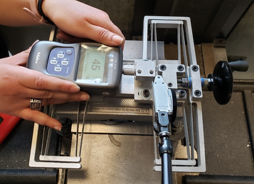
All components of the lathe were manufactured using a manual lathe and vertical mill. Once the components were assembled, tests were conducted to verify that the systems met their functional requirements. An image of all of the manufactured components and of stiffness testing (conducted with a force gauge and a dial indicator) can be seen below.


Results
At the end of the class, our team competed in a machining competition that involved turning five parts to a set diameter. Points were awarded based on repeatability, material removal rate, and lack of part taper. Our team placed first in the competition out of five other teams, making parts that were repeatable to 50 microns and had the least amount of taper.


.jpg)